


CAN bus (Controller Area Network) is a communication system used in vehicles/machines to allow ECUs (Electronic Control Units) to communicate with each other – without the need for a host computer. For example, CAN bus allows for fast and reliable sharing of information between a vehicle's brakes and engine.
Imagine your car like a human body:
CAN bus is nervous system allow communication
In turn, the ECU (also known as 'CAN node') is like the parts of the body, connected to each other via the CAN bus. Information sensed by one part can be shared with another.
Physically, all ECUs are connected on a two-wire bus consisting of a twisted pair of wires: CAN high and CAN low. The wires are usually color-coded: CAN high is yellow (resembling the sun), CAN low is green (resembling grass).

PEAK System PCAN-USB CAN USB Adapter

The PCAN-USB interface allows simple connection to the CAN network. Its compact plastic housing makes it suitable for portable applications. The opto-decoupled version ensures galvanic isolation of up to 500 Volts between the PC and the CAN side. The PCAN-View monitoring software and the PCAN-Basic programming interface for developing CAN-connected applications are included in the scope of supply and support CAN FD. Device drivers exist for various operating systems, so programs can easily access the connected CAN bus.

Electronic control units (ECUs) are components that control certain functions – for example, the engine, transmission, brakes, steering, temperature, etc. A modern car can easily have more than 70 ECUs – each ECU shares information with other ECUs on the bus.
Any ECU on the CAN bus can prepare and transmit information (e.g. sensor data). The transmitted data is accepted by all other ECUs on the network – and each ECU can then examine the data and decide whether to accept or ignore it.
If we zoom in, the ECU consists of three main components:


How to connect to CAN bus?
There is no standard connector for CAN bus applications. As we will show later, this means that different vehicles/machines may use different connectors.
However, a close candidate is the CAN DB9 (D-sub9) connector (CANopen CiA 303-1), which has become the de facto standard for many applications including CAN bus data logger/interfaces.

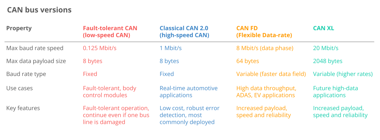
Before we continue, we need to know that there are many variations of CAN:
The CAN bus standard is used on most vehicles and many machines because of the following key benefits:

ECUs communicate via a single CAN system instead of via complex direct analog signal paths – reducing errors, weight, wiring and cost

The CAN bus provides a 'single entry point' to communicate with all network ECUs – allowing central diagnostics, data logging and configurationDetails

The system is resistant to electromagnetic interference and electromagnetic interference – ideal for safety-critical applications (e.g. vehicles)Details

CAN frames are prioritized by ID so that data with the highest priority accesses the bus immediately without interrupting other frames.

Today, CAN is standard in automobiles ( car , truck , buses, tractors, …), ship , plane, EV batteries , machines , etc.


Looking forward, the CAN bus protocol will remain relevant – although it will be affected by major trends :
Open vs. Closed: The push for 'Open Source' and possibly against OEM-driven demands for proprietary data to, for example, provide subscription-based microservices
Need for speed: The need for higher data rates could drive the transition to CAN FD, CAN XL, or Automotive Ethernet
Please contact SEMIKI to get advice on choosing the right CAN device lines for your needs
CONTACT:
SEMIKI Measuring Equipment Company Limited
Email: [email protected]
Phone: +84 9797 61016


